
Introduction: How to provide a community Internet service using the Guest Internet STAR-4 kit

The STAR series of kits are designed to share the Starlink Internet service with a community and provide wireless connections for homes up to 1 Km from the location of the Starlink antenna. The Starlink antenna is connected to the Guest Internet controller and a powerful wireless access point connects to the Guest Internet controller. There are four STAR kits that can be connected to the Starlink antenna router, the STAR-1, 2, 6 and 7. The difference between these kits is the performance and the number of people that can be connected.
Each home that requires an Internet connection has a STAR-4 kit installed that communicates with the Guest Internet controller wireless access point.

The STAR-4 kit has two parts, the WCW-1 wireless receiver that is installed on the home roof. This receiver must have a clear line of sight to the STAR wireless antenna at the location of the Starlink antenna. The WCW-1 wireless receiver is connected to the WWR-1 wireless router inside the home. The home residents connect WiFi devices to the WWR-1 WiFi to get Internet access.
The STAR-4 kit has the products to install two homes. The installer must provide the Ethernet cable that connects the WCW-1 to the PoE power inside the home.
This document explains how to install and configure the STAR-4 kit.
Alignment of the WCW-1 antenna
The STAR-4 kit contains two WCW-1 wireless products and two WWR-1 wireless routers. Each home has one WCW-1 and one WWR-1. The STAR-4 kit has the products for two homes.
The WCW-1 is a wireless antenna installed on the home roof that communicates with the STAR-1, 2, 6, or 7 kit that is located with the Starlink antenna. The WCW-1 must have a clear line of sight to the STAR antenna. The WCW-1 connected to the WWR-1 wireless in the home that provides the WiFi Internet for devices. The installer must provide the outdoor Ethernet cable that connects the WCW-1 to the power inside the home.

The WCW-1 product is configured first. The antenna is directional and must point towards the STAR wireless controller. The distance should be less than 1Km with line of sight. The direction of antenna transmission is shown in the figure.

The STAR-4 kit products are already configured to work with the STAR-1, 2, 6 and 7 kits
Most installations of the STAR-4 kits with the STAR-1, 2, 6 and 7 kits do not require configuration as the products are configured for the default settings. The installer can skip the configuration steps and proceed to the test steps.
When the STAR-4 kit will be used with any other manufacturers product then configuration will be required.
The STAR-4 kit WCW-1 wireless receiver default configuration characteristics are as follows.
- The WCW-1 wireless receiver connects to a wireless name (SSID) of: Hot Spot. The STAR-1, 2, 6 and 7 kits are pre-configured to broadcast the SSID Hot Spot. If the configuration of the STAR-1, 2, 6 or 7 kit SSID is change then the WCW-1 will also require configuration for the new SSID.
The STAR-4 kit WWR-1 wireless router default configuration characteristics are as follows.
- The WWR-1 broadcasts the SSID of: HomeWiFi
- The WWR-1 broadcast encryption key (WPA) is: 66666666
- The WWR-1 is configured for the Guest Internet login page: aplogin.com
If the installer wishes to change any parameter then the WWR-1 must be configured. If there is no change then proceed to the test section.

How to set a Windows computer to a static IP address
The WCW-1 and WWR-1 products are shipped pre-configured, however it may be necessary to configure them. To configure the WCW-1 and WWR-1 products it is necessary to set the computer LAN port for a static IP address.
Open the settings page, select network and Internet.

Select Ethernet then change adapter options.

Right click on Ethernet then select properties.

Select Internet protocol version 4 then click properties.

Select use the following IP address
Enter the IP address: 192.168.188.10
Enter the subnet mask: 255.255.255.0
Click the OK button.

Finally click close. The LAN port can now be connected to the WCW-1 and WWR-1 products to configure them.

WCW-1 Configuration
Set the switch to ‘C', (CLIENT), power the WCW-1 via the PoE supply provided.
Install on the roof.
Point the WCW-1 Client antenna to the central wireless access point antenna; the STAR-1, 2, 6 or 7 kit.

Configure the computer to a static IP address: 192.168.188.10. Open a new browser tab on the configuration computer. Type the following IP address in the browser tab then press enter.
192.168.188.100
A box will open for the username and password, the default password is ‘admin’, enter the password and click login.
The home page is displayed below.

Click the WiFi page icon, the display is shown in the next figure.

Click the tab repeater settings. Click the scan button, select the SSID of the STAR wireless access point from the list by clicking it. The default SSID is Hot Spot
Go to the password box, enter the WPA key that is configured in the Host. Click apply.

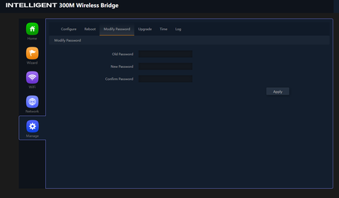
Continue with the WiFi page, click the advanced tab. Set the country. Click apply.

Click the manage icon, click the modify password tab. Enter the new password, make a note of the password. Click apply.
Configuration of Client is complete.
Test the WCW-1 connection to the central antenna: The wireless connection to the STAR-1, 2, 6, or 7 kit
At this point the WCW-1 antenna is installed on the home roof, and the configuration shows that the wireless is connected to the STAR wireless access point antenna. The next step is to test the Internet connection to the STAR wireless access point using a computer.
Set computer LAN port to DHCP using the instructions provided at the beginning of this document. Connect the computer LAN port as shown in the diagram.
Open a browser window then open a new tab and type: aplogin.com
The login page from the STAR-1, 2, 6, or 7 kit should open, this is shown in the figure. If this page does not open then check the STAR-1, 2, 6, or 7 WiFi connections using a mobile device to check that the login page opens. If it does then repeat the WCW-1 configuration process to connect to: Hot Spot

WWR-1 Configuration
When the WCW-1 wireless receiver has been installed and tested the WWR-1 wireless router can be configured and installed. The WCW-1 is pre-configured with the following characteristics.
- Wireless name (SSID): HomeWiFi
- Wireless WPA key (encryption): 66666666
To configure the WWR-1, connect the WWR-1 product to the power supply and computer as shown in the diagram.

Configure computer for static IP using the instructions provided previously.
- Set Static IP to: 192.168.188.10
- Set Netmask to: 255.255.255.0
Connect the computer LAN port to the WWR-1 LAN port
Open a new browser tab on the computer, type the following IP into the browser tab:
- 192.168.188.253
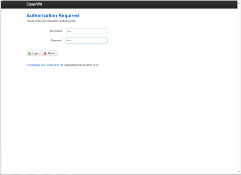
The login box will open, provide the username and password.
- username: root
- password: admin
Click the login button, shown on the next screen.
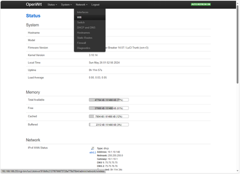
After login the status page is displayed.

Click the network tab then select WiFi from the drop down menu and click.
The Network WiFi page will open; click the edit button.

The wireless name (called ESSID) is set to the default of HomeWiFi. This can be changed to any other name. This name will appear when people search for WiFi networks.

If a change is made click save & apply.

Click the wireless security tab to set the WiFi encryption key. Enter the WiFi encryption key desired (the default is 666666), make a note of the key. Then click save & apply.

Click the network DHCP and DNS tab. Look for the domain white-list box. The domain white-list default is set to aplogin.com. If this has not been set then set to aplogin.com to allow the home computers to connect to the login page.

If there was any change click save & apply.

Configuration of the WWR-1 is complete.
Unplug the power supply then plug the power supply again to reboot the WWR-1.
Get a computer or mobile phone and look for WiFi networks. Verify that the WWR-1 wireless name (SSID) is displayed: HomeWiFi
Enter the WPA key that was selected: (default is 66666666)
Verify that the device can connect to the WiFi.
Proceed to the next section, verify that a device connecting to the WWR-1 WiFi can open the login screen of the STAR-1, 2, 6, or 7 kit controller.
Test the WiFi network connection with STAR-2 and STAR-4 kits
Connect the equipment as shown in the figure. Connect the computer or mobile device to the WWR-1 WiFi signal: HomeWiFi
Now open a computer browser then open a new browser tab.
Type the name of the Guest Internet controller: aplogin.com then the login page should open. If the login page does not open then go back a few steps to the beginning. Test the WCW-1 connection to the STAR kit antenna, then proceed to repeat the test with the WWR-1 connected to the WCW-1.

Test the Internet access using an access code generated using the Guest Internet controller.
With the computer or mobile device connected to the WiFi of the WWR-1, open a browser to see the login page, an example of a login page is shown in the next figure.
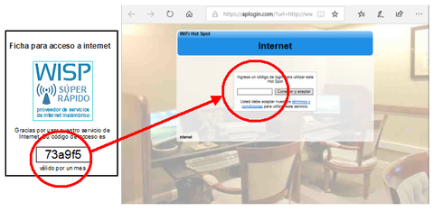
The code on the voucher is typed into the login page then the button is clicked. If the code is valid then the computer will have access to the Internet.
If the login page opens but the code is not accepted then test that the access is available at the STAR-1, 2, 6, or 7 kit as shown in the next figure.

Add the second home to WiFi network configuration with the STAR-4 kit
When the first home has been installed and is providing Internet access proceed to install the second home using the second WCW-1 and WWR-1 provided with the kit. The procedure is identical to the first home.
Provide each home with an access code printed onto a voucher. The procedure for printing vouchers with access codes is included with the STAR-1, 2, 6 and 7 kit information.

Expand your network by adding more homes
After successfully installing the first home and connecting it to a STAR access point kit, proceed to install more homes. Each STAR-4 kit has the equipment to install two homes. There is a limit to the number of homes that is determined by the STAR kit wireless access point capacity, the bandwidth of the Starlink antenna, and the maximum data speed allocated to each home. The Star kit capacity is as follows:
- STAR-1: no limit but 30 homes is suggested maximum
- STAR-2: no limit but 50 homes is suggested maximum
- STAR-6: no limit but 75 homes is suggested maximum
- STAR:7: no limit but 100 homes is suggested maximum
Calculate the bandwidth or maximum data speed by dividing the maximum speed of the Starlink antenna by the number of homes. The Starlink antenna provides 200Mb/s so for 50 homes:
- 200 / 50 = 4Mb/s maximum speed limit set for each home access code
The diagram shows 4 homes connecting to a STAR kit wireless access point.
